
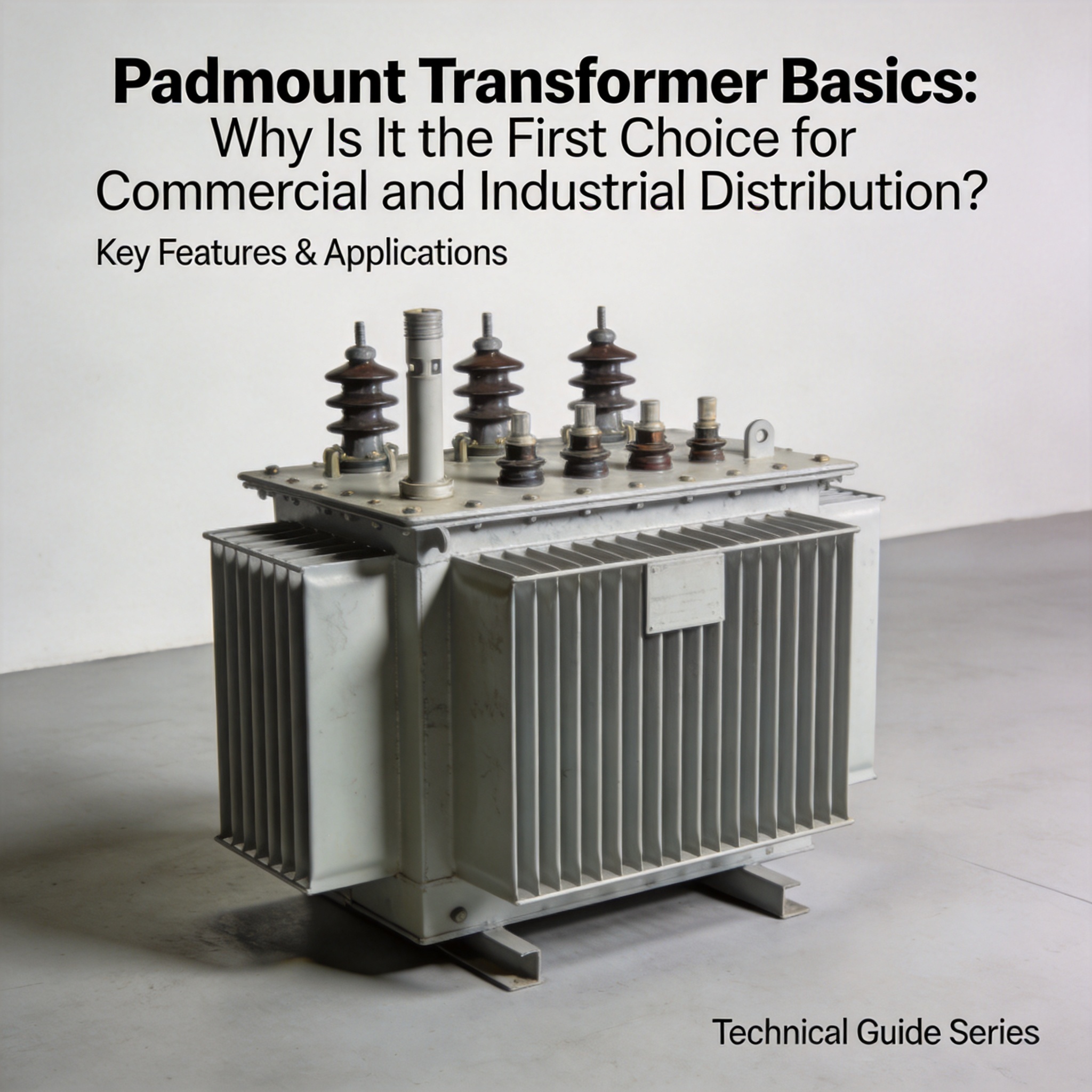
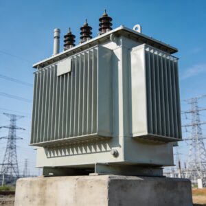
A padmount transformer is a ground-level electrical transformer enclosed in a locked, tamper-resistant metal cabinet and mounted on a concrete pad. It steps medium-voltage power (typically 2.4 kV to 34.5 kV) down to the low-voltage supply your building uses (120/208 V, 277/480 V, or 347/600 V). Because the enclosure sits directly on the ground, it is called “pad-mounted.” After reading this guide, you will be able to identify padmount types, size a unit for a commercial load, prepare a site, and avoid the four mistakes that cause most inspection failures.
Table of Contents
1. How a Padmount Transformer Works
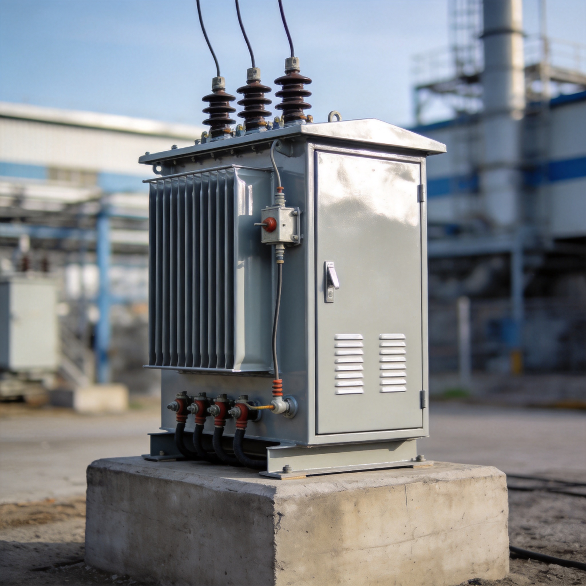
A padmount contains two isolated compartments separated by a steel barrier. The high-voltage compartment holds the primary terminations, bayonet fuses, and load-break elbows. The low-voltage compartment holds the secondary bushings, neutral bar, and customer connections. Utility workers open the primary side; a licensed electrician opens the secondary side. This separation is the core safety feature.
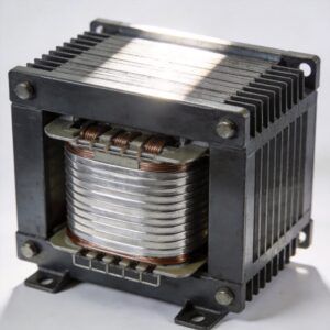
Inside the tank, a laminated steel core and copper or aluminum windings form the magnetic circuit. When primary current flows through the high-voltage winding, it induces a lower voltage in the secondary winding at the turns ratio. A 13.8 kV to 480 V unit has a ratio of roughly 28.75:1. Mineral oil or a dry-type epoxy filling cools the windings and insulates them from the tank wall.
Three physical configurations exist, and the naming is literal:
- Radial — one primary feed; used where a single utility circuit is acceptable.
- Loop — two primary feeds with taps; allows the utility to back-feed the transformer from either direction during outages. Standard for commercial sites.
- Dead-front — all live primary parts are shielded behind insulated elbows, so no exposed high-voltage metal is reachable. Nearly all modern commercial units are dead-front.
Typical stock sizes run 75 kVA, 150 kVA, 300 kVA, 500 kVA, 750 kVA, 1000 kVA, 1500 kVA, 2000 kVA, and 2500 kVA. Single-phase units cover 15–167 kVA. Mineral-oil-filled units dominate outdoor commercial use; dry-type units appear where fire codes restrict flammable liquid, such as indoor vaults.
2. Why It Is the First Choice for Commercial and Industrial Distribution
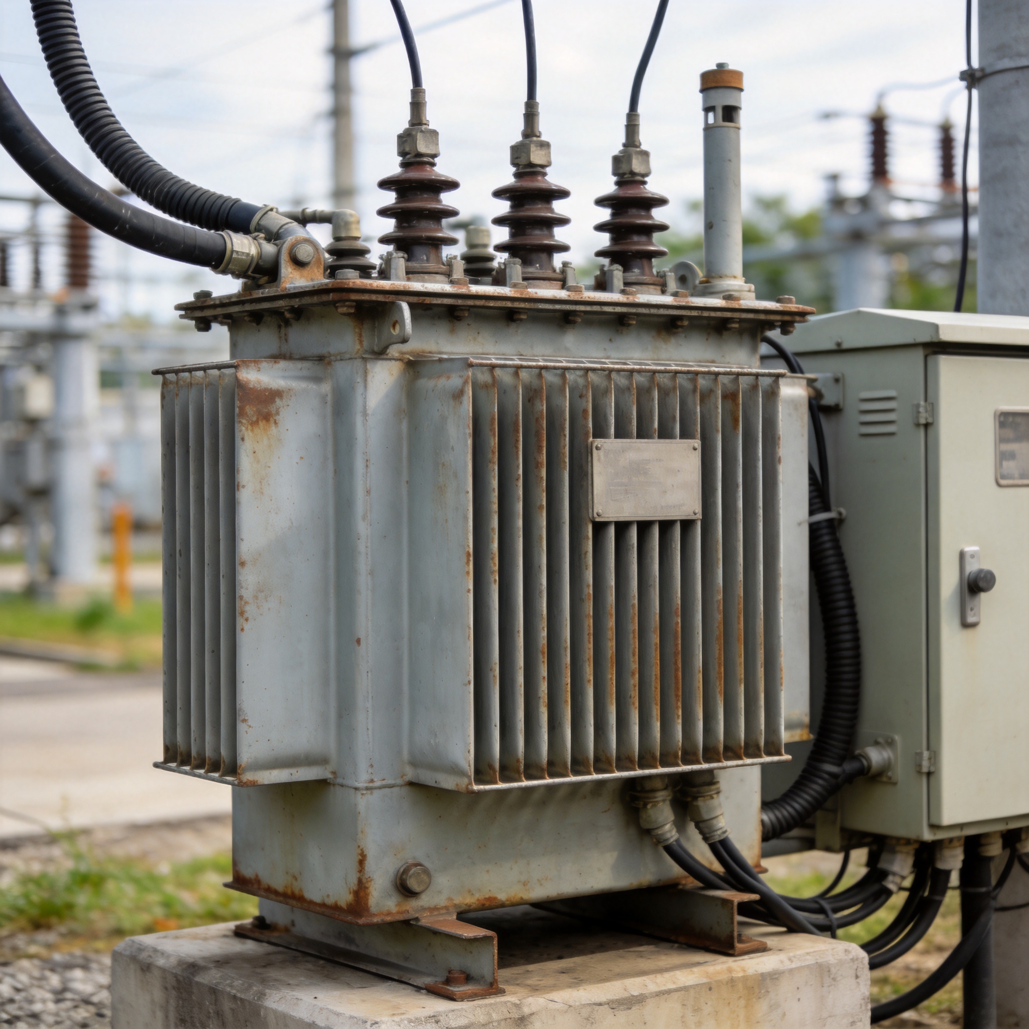
The short answer is land cost versus enclosure cost. A padmount occupies roughly 1.2 m × 2.4 m (4 ft × 8 ft) of ground and needs about 3 m (10 ft) of clear working space in front of the doors. A comparable vault or indoor substation consumes a dedicated room inside the building, and that room must be fire-rated, ventilated, and sprinklered. On a commercial project, the interior square footage you save is often worth more than the transformer itself.
Four practical advantages follow from that:
- No building penetration for the primary. The utility terminates outside the structure, so the owner’s electrical contractor never touches medium voltage.
- Faster energization. Utility crews can loop and fuse the unit without coordinating an interior vault inspection.
- Simpler maintenance. Oil sampling, gauge checks, and fuse replacement all happen outdoors with no confined-space entry permit.
- Design flexibility. The unit can be relocated if the site layout changes, which is nearly impossible with a built-in vault.
Cost is the counterweight. As a planning figure, a 500 kVA oil-filled padmount typically runs in the range of USD 8,000–15,000 for the equipment alone, before pad, conduit, cable, and utility connection fees. A vault installation of the same rating often exceeds that once fire-rated construction is included. Treat these as order-of-magnitude figures and confirm with a local supplier, because lead times and copper prices swing the number significantly.
Two standards govern the hardware. In North America, IEEE C57.12.34 sets the dimensional and electrical requirements for three-phase pad-mounted compartmental-type transformers. ANSI C57.12.00 covers general requirements for distribution transformers. In Canada, CSA C227.4 applies to single-phase units and CAN/CSA-C227.3 to three-phase units. If you are specifying a unit, ask the supplier to confirm compliance with the standard your utility requires, because utilities often add their own dimensional preferences on top.
3. How to Size and Specify One: Step by Step
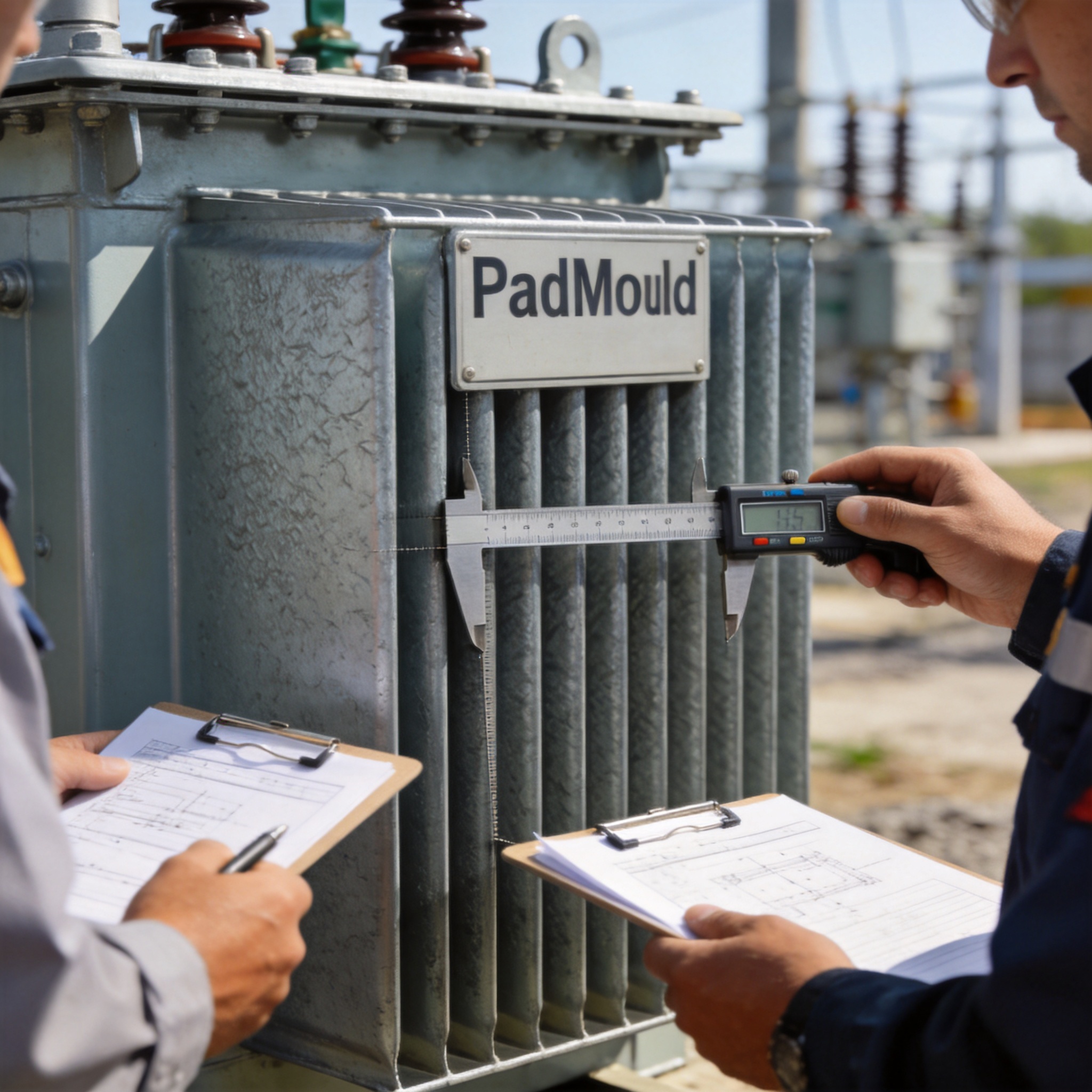
Follow these steps in order. Each one produces a number you carry into the next.
- Total your connected load in kVA, not kW. Sum the nameplate kVA of every load. For motors, use the nameplate kVA rather than horsepower. For a mixed commercial building, a lighting and receptacle load of 200 kW at 0.9 power factor equals 222 kVA.
- Apply the demand factor. You do not size for 100% of connected load. NEC Article 220 allows demand factors; a common office figure is 0.8, an industrial plant with continuous process load may be 0.9 or higher. 222 kVA × 0.8 = 178 kVA.
- Add 25% headroom for future load. Commercial tenants add equipment. 178 kVA × 1.25 = 222 kVA.
- Round up to the next standard size. 222 kVA lands on a 300 kVA unit. Never round down; a transformer run above nameplate will overheat and shorten its insulation life.
- Check the impedance for your fault current. A typical padmount has 2%–6% impedance. Lower impedance means higher available short-circuit current at the secondary, which affects your panel’s interrupting rating. Ask the supplier for the impedance value before you order switchgear.
- Confirm the primary voltage and connection type with the utility. Give them your calculated kVA and your secondary voltage. They will tell you the primary voltage, whether the unit is loop or radial, and their required pad dimensions.
- Specify the pad and clearances. Pour a reinforced concrete pad per the utility’s drawing, typically 100–150 mm (4–6 in) thick. Maintain the utility’s required front clearance, usually 3 m (10 ft), and side clearance, usually 1.5 m (5 ft). Keep the pad above the local flood elevation.
- Install grounding per code. Drive ground rods at the pad corners and bond the tank, the neutral, and the secondary grounding electrode system together. NEC Article 250 governs this; the utility will inspect it before energizing.
- Coordinate bollards and drainage. Place protective bollards where vehicles can strike the cabinet, and grade the pad so water drains away from the doors. Standing water at the base accelerates tank corrosion.
For the load calculation rules themselves, the authoritative source is NFPA 70, the National Electrical Code, Article 220. NFPA publishes the free-access edition at nfpa.org. For transformer testing and loss evaluation, the U.S. Department of Energy maintains efficiency standards for distribution transformers at energy.gov.
4. Common Mistakes and Fixes
These four problems account for most failed inspections and premature failures I have seen on commercial projects over 28 years of transformer work.
| Mistake | Symptom | Fix |
|---|---|---|
| Sizing on kW instead of kVA | Unit runs hot; oil analysis shows elevated dissolved gas within 2 years | Recompute using nameplate kVA and power factor; upsize one standard step |
| Ignoring working clearance | Inspector rejects the installation; utility refuses to energize | Re-pour or relocate the pad to restore the full front clearance |
| Undersized or missing grounding | Neutral-to-ground voltage drift; nuisance trips on sensitive equipment | Install ground rods at all corners and bond per NEC Article 250 |
| No bollards in a drive aisle | Dented cabinet, cracked bushings, oil leak after vehicle impact | Install steel bollards 1 m from the cabinet on the traffic side |
Mistake 1: Sizing on kW. The symptom appears slowly. A unit loaded at 110% of its kVA rating will not fail immediately, but its insulation degrades faster. The fix is a corrected load calculation; if the unit is already installed, add a second transformer or shift load to another service.
Mistake 2: Ignoring working clearance. This is the single most common rejection I have witnessed. The symptom is immediate: the utility will not connect. The fix is physical — move the pad. Do not attempt to negotiate clearance with the utility; their dimensions come from arc-flash and safe-work rules.
Mistake 3: Undersized grounding. The symptom is subtle electrical noise and intermittent equipment faults. The fix is a proper grounding electrode system bonded to the tank and neutral, inspected before energization.
Mistake 4: No bollards. The symptom is a repair bill and a service outage. The fix is cheap: install bollards before the site is paved, not after.
5. FAQ
Who owns and maintains the padmount transformer? In most commercial installations, the utility owns the transformer and the primary cable; the building owner owns the pad, the secondary conductors, and the customer-side terminations. Confirm ownership in writing before construction, because it determines who pays for replacement.
Can I install one indoors? Only if the unit is dry-type or the space is a code-compliant vault with fire-rated walls, ventilation, and drainage. Oil-filled units indoors require a vault that meets NEC Article 450. Most projects choose an outdoor padmount specifically to avoid this cost.
How much space do I need? Plan for the pad footprint plus the utility’s front clearance, typically 3 m (10 ft), and side clearance of about 1.5 m (5 ft). A 500 kVA three-phase unit commonly needs a pad around 1.5 m × 2.5 m (5 ft × 8 ft). Get the exact dimensions from your utility’s standard drawing.
How long does one last? A mineral-oil padmount in a well-drained location with normal loading typically serves 25–35 years. Heat, moisture, and sustained overload are the three factors that shorten that life. Annual oil testing catches most degradation early.
What is the difference between a padmount and a pole-mounted transformer? A pole-mount hangs on an overhead line and serves smaller loads, generally up to 167 kVA single-phase. A padmount sits on the ground, can be three-phase, and reaches 2500 kVA or more. Underground commercial distribution uses padmounts because there is no pole to hang from.
Do I need a permit? Yes. You will need a local electrical permit and, in most jurisdictions, a separate utility service application. The utility reviews the load calculation, the pad drawing, and the grounding plan before approving energization.



 English
 Français
 Español
 Deutsch