
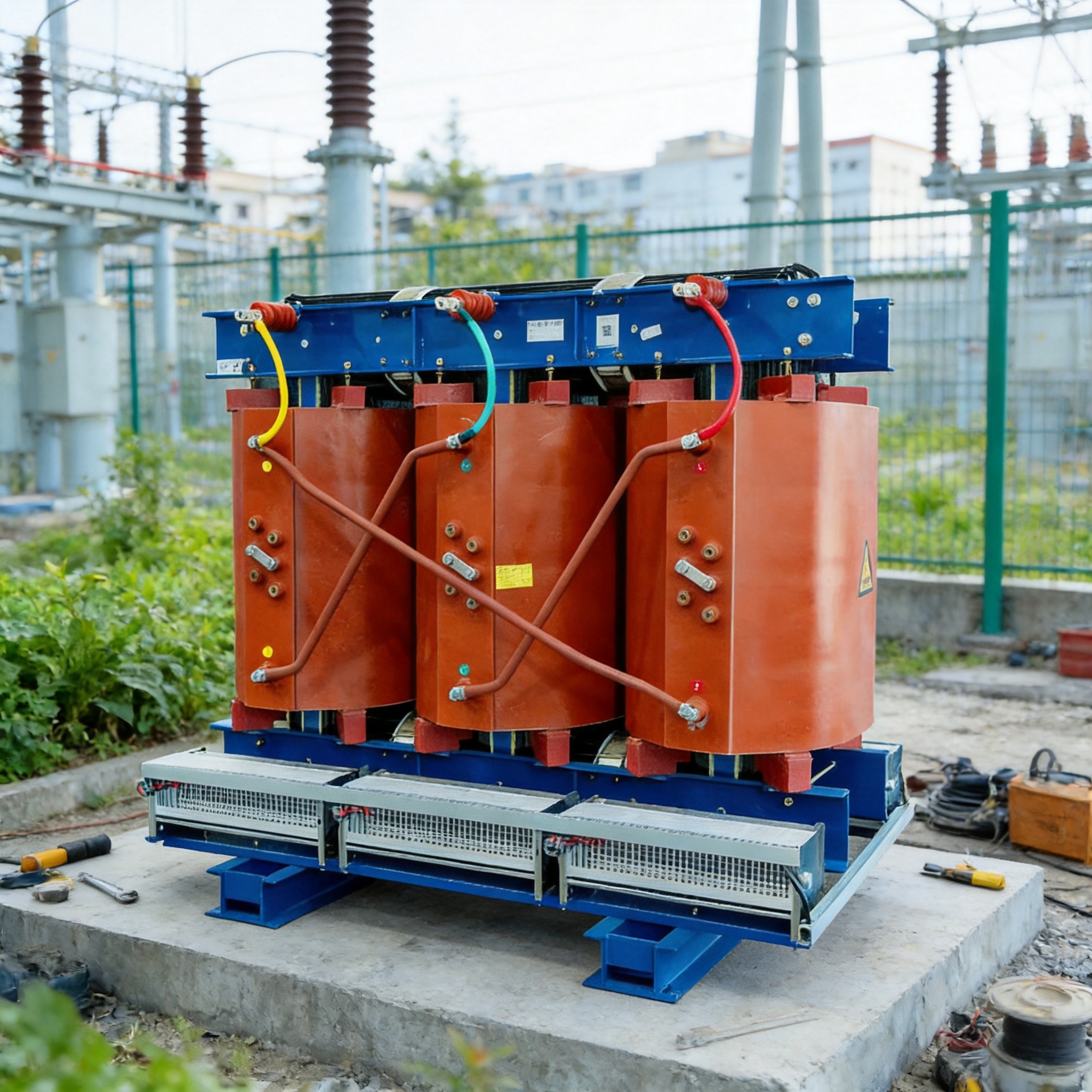
Partial discharge (PD) testing for dry-type transformers is an electrical diagnostic method that detects small, localized electrical sparks occurring inside or on the surface of insulation. These discharges do not bridge the full insulation gap, but they gradually erode it. A PD test measures the magnitude (in picocoulombs, pC) and location of these discharges. Because solid cast-resin insulation cannot self-heal like oil, PD is the earliest and most reliable indicator that a dry-type transformer’s insulation is degrading. After reading this article, you will be able to explain why PD matters, perform a basic PD measurement following a step-by-step procedure, and recognize the three most common testing mistakes.
Table of Contents
Why Partial Discharge Predicts Insulation Quality
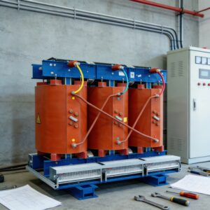
Dry-type transformers such as the SCB series (30–5000 kVA, insulation class F or H) use cast epoxy resin as both dielectric and mechanical support. Unlike oil-immersed units, there is no liquid to absorb or disperse local stress. Any void, delamination, or contaminant inside the resin creates a region of lower dielectric strength.
When the applied voltage exceeds the breakdown strength of that weak region — but not the full insulation — a partial discharge occurs. Each discharge event deposits heat and charged particles on the void wall. Over months or years, the void grows into a tree-like channel. Eventually the channel bridges the insulation and causes a flashover.
The key point: PD activity appears long before the transformer fails. A unit can pass a power-frequency withstand test and still show 500 pC of discharge. That is why IEC 60076-11 and EN 50588-1 set PD limits for dry-type transformers rather than relying on withstand tests alone. For rated voltages up to 35 kV (insulation levels LI170 AC70/AC5 at 35 kV, LI125 AC50/AC5 at 20 kV, LI75 AC35/AC5 at 10 kV), the typical acceptance limit is 10 pC at 1.3× rated voltage for cast-resin units. A reading above that limit means the insulation quality is not acceptable, even if the unit “works.”
What the PD magnitude tells you
| PD Level (pC) | Interpretation | Action |
|---|---|---|
| < 10 | Normal for new cast-resin units | Accept |
| 10–100 | Minor voids or surface contamination | Investigate, retest after cleaning |
| 100–500 | Active internal defect | Locate source, plan repair or replacement |
| > 500 | Severe degradation, high failure risk | Remove from service |
These thresholds are diagnostic guidance, not a substitute for the manufacturer’s specification. Always confirm against the nameplate and the applicable standard (IEC 60076-11, EN 50588, or UL for the relevant market).
How to Perform a PD Test: Step-by-Step
The following procedure covers an offline PD measurement using a conventional PD detector with a coupling capacitor. It assumes the transformer is de-energized, isolated, and grounded. You need: a calibrated PD detector, a coupling capacitor rated above the test voltage, a calibration pulse generator, and a shielded test cable.
- Isolate and ground the transformer. Open the upstream breaker, apply lockout/tagout, and ground all high-voltage and low-voltage terminals. Verify zero voltage with a rated detector before touching any connection.
- Disconnect external cables. Remove the HV and LV cable connections so that external noise and capacitance do not distort the measurement. Record the connection group (e.g., Dyn11 or Yyn0) so you can restore it correctly.
- Connect the coupling capacitor. Attach the coupling capacitor to the HV terminal under test. Connect its low side to the PD detector input. Keep the cable as short as possible and route it away from the floor.
- Calibrate the circuit. Inject a known charge (for example, 100 pC) with the calibration pulse generator at the HV terminal. Adjust the detector until the reading matches the injected value. Record the calibration factor. Do not skip this step — an uncalibrated reading is meaningless.
- Raise voltage gradually. Increase the test voltage from zero to 1.3× rated voltage at a rate you can control (roughly 1 kV per second). At each of these levels, hold for one minute and record the PD reading: 0.5×, 0.8×, 1.0×, 1.3× rated voltage.
- Record the PD inception and extinction voltages. Note the voltage at which PD first appears (PDIV) and the voltage at which it disappears on the way down (PDEV). A large gap between PDIV and PDEV indicates a stable defect.
- Reduce voltage to zero and discharge. Lower the voltage slowly, then ground the HV terminal through a discharge resistor before removing any connections.
- Compare against the limit. If the reading at 1.3× rated voltage exceeds 10 pC (for cast-resin dry-type units), the insulation fails the PD criterion. Log the value, the test voltage, and the ambient conditions.
For a 10 kV SCB unit, the test voltage at 1.3× is 13 kV. For a 35 kV unit, it is 45.5 kV. Confirm these values against the insulation level on the nameplate (LI75 AC35/AC5, LI125 AC50/AC5, or LI170 AC70/AC5) before you begin.
Common Mistakes and How to Fix Them
Mistake 1: Testing in a noisy environment
Symptom: The detector shows 50–200 pC even with no voltage applied, or the reading jumps randomly. Fix: Turn off nearby welding equipment, fluorescent lights, and variable-frequency drives. Perform a background noise check with voltage at zero. If background noise exceeds 5 pC, move the test to a shielded room or use a detector with noise gating. Never subtract noise from a live reading — it is not a linear correction.
Mistake 2: Skipping calibration
Symptom: Readings look plausible but cannot be compared between tests or between transformers. Fix: Always inject a known charge before each test session. Recalibrate if you change the cable length or the coupling capacitor. A reading without a recorded calibration factor is not evidence of anything.
Mistake 3: Testing only at rated voltage
Symptom: A unit passes at 1.0× rated voltage but fails in service within a year. Fix: Test at 1.3× rated voltage as required by the standard. Defects that are dormant at rated voltage often activate at the higher stress level. Record the full voltage sweep, not just one point.
Mistake 4: Ignoring surface discharge
Symptom: High PD reading that disappears after cleaning the bushings and terminal blocks. Fix: Clean all external insulation surfaces with isopropyl alcohol and retest. Surface discharge is a maintenance issue, not an internal defect, but it masks the internal reading if left untreated.
FAQ for Beginners
What is a normal partial discharge level for a dry-type transformer?
For new cast-resin dry-type transformers rated up to 35 kV, the accepted limit is 10 pC at 1.3× rated voltage. Readings below 10 pC indicate sound insulation. Anything above that requires investigation.
How often should I perform PD testing?
Perform PD testing at commissioning, then every 1–3 years depending on load and environment. If a reading rises by more than 50% between tests, shorten the interval to every 6 months and investigate the cause.
Can I do a PD test while the transformer is energized?
Online PD testing is possible using permanently installed sensors, but it requires different equipment and interpretation. The step-by-step procedure above is an offline test. For online monitoring, consult a qualified professional.
Does a high PD reading always mean the transformer must be replaced?
No. Surface contamination, loose connections, and moisture can all raise PD readings and are correctable. Only internal defects in the cast resin — confirmed by locating the discharge source — require replacement. Always clean, retest, and locate the source before deciding.
What standards govern PD testing for dry-type transformers?
The main references are IEC 60076-11 (dry-type power transformers), EN 50588-1 (medium power transformers), and UL requirements for the relevant market. These define the test voltage, the acceptance limit, and the measurement method.
For further reading on dielectric test methods, see the IEEE standards catalog and the IEC webstore.



 English
 Français
 Español
 Deutsch