
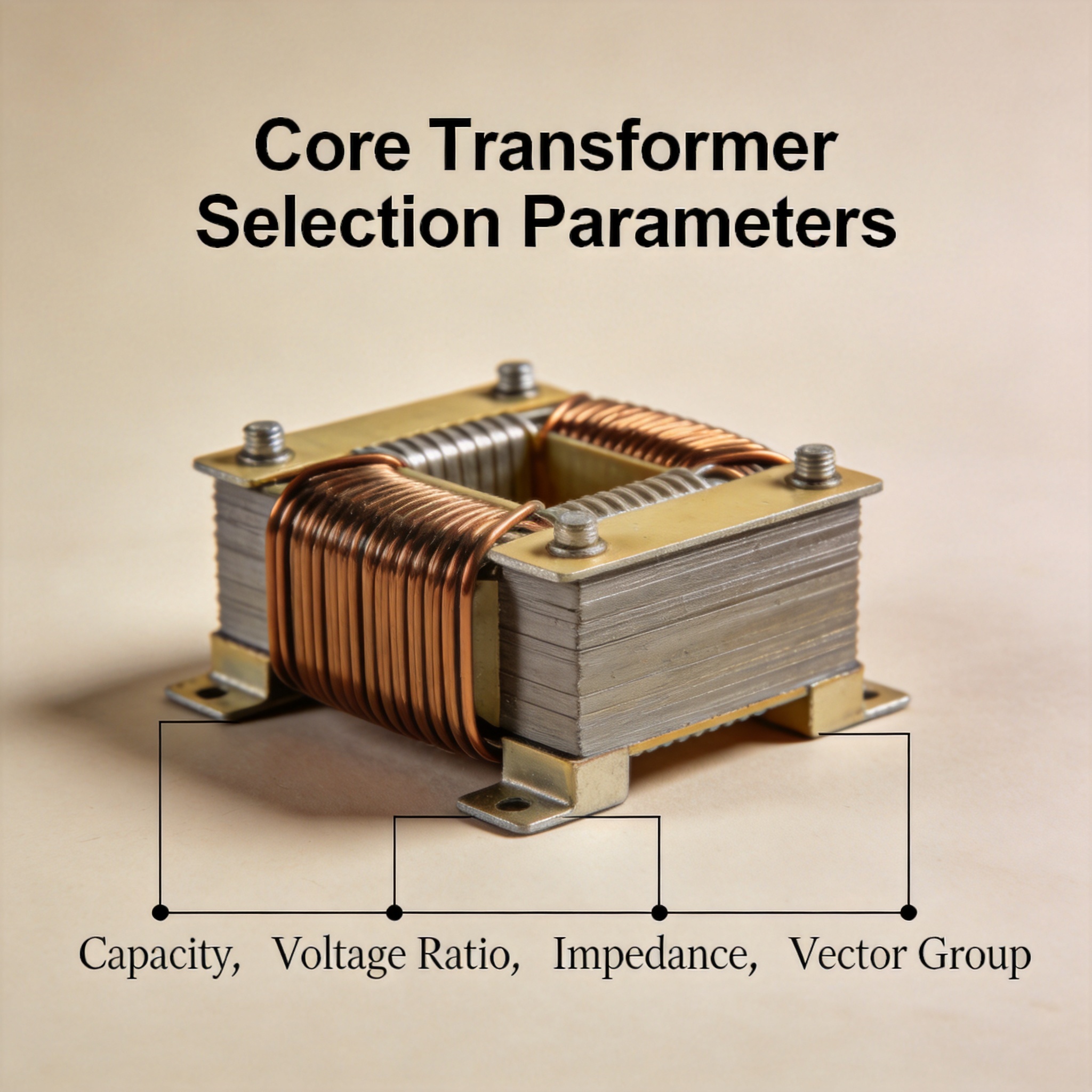
The four core transformer selection parameters are capacity (kVA rating), voltage ratio (primary/secondary turns ratio), impedance (percent Z), and vector group (winding phase displacement). Capacity tells you how much load the transformer can carry, voltage ratio matches it to your system voltages, impedance controls fault current and voltage drop, and vector group ensures phase compatibility with the rest of your network. By the end of this article, you will be able to read a load schedule and a nameplate, then calculate and specify all four parameters for a real transformer order.
Table of Contents
How the Four Parameters Work Together
Think of the four parameters as four questions answered in sequence. Capacity answers “how big?” — it is the apparent power (kVA) the transformer can deliver continuously without exceeding its temperature rise limit. Voltage ratio answers “at what voltages?” — it is set by the turns ratio between primary and secondary windings and must match your source and load voltages.
Impedance answers “how does it behave during a fault?” — expressed as a percentage, it is the voltage drop across the transformer when full rated current flows through a short circuit. A 5% impedance means 5% of rated voltage drives full-load current into a bolted fault. Vector group answers “which way do the phases point?” — it defines the phase angle relationship between primary and secondary, such as Dyn11 (30° lag) or Yyn0 (0° displacement).
The parameters interact. A higher impedance reduces fault current but increases voltage drop under load. A larger capacity reduces loading percentage but raises cost and no-load losses. Vector group is not negotiable for paralleling — two transformers with mismatched vector groups cannot be operated in parallel, regardless of how well the other three parameters match.
How to Select Each Parameter (Step by Step)
Step 1: Calculate Required Capacity (kVA)
Sum your connected loads in kW, then divide by the power factor to get kVA. Apply a future-growth margin of 20–25%. For a facility with 640 kW of connected load at 0.8 power factor: 640 ÷ 0.8 = 800 kVA, then 800 × 1.2 = 960 kVA. Select the next standard size, 1000 kVA.
- Continuous loads: use 100% of nameplate kVA.
- Motor loads: add starting kVA if across-the-line starting is used.
- Standard sizes (IEC 60076): 100, 160, 250, 400, 630, 1000, 1600, 2500 kVA.
Step 2: Fix the Voltage Ratio
Read your system voltages from the single-line diagram. A typical medium-voltage distribution transformer might be 11,000 V / 433 V. Confirm the ratio against the turns ratio formula: V₁/V₂ = N₁/N₂. Check that the secondary voltage stays within ±5% of nominal at your actual tap setting. Most distribution transformers offer ±2 × 2.5% taps on the primary to correct for supply variation.
Step 3: Specify Percent Impedance
Impedance is normally chosen from standard values, not calculated from scratch. Use this decision rule: for transformers ≤ 630 kVA, specify 4%; for 630–2500 kVA, specify 5–6%; for larger units, 6–8%. Higher impedance limits fault current, which lets you use lower-rated switchgear. Verify the resulting voltage drop:
Voltage drop (%) ≈ %Z × load fraction × sin(φ)
At 5% impedance, 80% loading, and 0.8 power factor (sin φ = 0.6): 5 × 0.8 × 0.6 = 2.4% drop. That is acceptable for most distribution systems.
Step 4: Choose the Vector Group
Match the vector group to your earthing and load requirements. Use this table as a starting point:
| Vector Group | Phase Displacement | Typical Use |
|---|---|---|
| Dyn11 | 30° lag | Distribution, allows neutral for single-phase loads, blocks zero-sequence harmonics |
| Yyn0 | 0° | Small distribution units, no parallel operation with Dyn11 |
| YNd11 | 30° lag | Generator step-up, transmission |
| Dd0 | 0° | No neutral required, industrial rectifier feeds |
Step 5: Cross-Check All Four Against the Nameplate
Before ordering, verify the four values against the intended duty. Confirm that capacity exceeds calculated demand, voltage ratio matches system voltages, impedance aligns with switchgear fault rating, and vector group matches any transformer you intend to parallel. If you plan to parallel two units, all four parameters plus tap position must be compatible.
Common Mistakes and How to Fix Them
Mistake 1: Sizing capacity from kW without the power factor. Symptom: the transformer runs above 100% load and overheats. Fix: always convert kW to kVA by dividing by power factor (typically 0.8–0.9) before selecting a standard size.
Mistake 2: Ignoring impedance when specifying switchgear. Symptom: the calculated fault current exceeds the breaker interrupting rating. Fix: raise %Z within the standard range for that kVA class, or upgrade the switchgear. Recheck voltage drop after any impedance change.
Mistake 3: Paralleling transformers with different vector groups. Symptom: massive circulating current at no load, tripped protection, or transformer damage. Fix: only parallel units with identical vector groups and compatible impedance (within ±10% of each other per IEEE C57.12.00 practice).
Mistake 4: Selecting a tap range that cannot cover supply variation. Symptom: secondary voltage drifts outside acceptable limits. Fix: confirm the utility’s actual voltage range and choose a tap range (e.g., ±2 × 2.5%) that covers it.
FAQ
What is the most important parameter when selecting a transformer? Capacity. If the kVA rating is too small, the transformer will overheat and fail regardless of how well the other three parameters are chosen. Fix capacity first, then voltage ratio, impedance, and vector group.
Can I change the voltage ratio after the transformer is built? Only within the tap range provided at manufacture. A transformer ordered as 11,000/433 V with ±2 × 2.5% taps can be adjusted roughly ±5% on the primary. It cannot be re-rated to a fundamentally different ratio without rewinding.
What does 5% impedance mean in plain terms? If you short the secondary and slowly raise the primary voltage, 5% impedance means full rated current flows when the primary reaches 5% of its rated voltage. It is a measure of how much the transformer limits fault current.
Why does vector group matter if voltages match? Because phase angle matters. Two transformers with a 30° displacement between them will produce a voltage difference across the paralleling switch, driving large circulating currents even with no load connected.
How do I know which vector group to pick? Match it to your earthing scheme and load type. If you need a neutral for single-phase loads, use Dyn11 or Yyn0. If you are feeding a rectifier or a delta load with no neutral, Dd0 works. Always confirm compatibility with any existing transformer you plan to parallel.
Verification and Sources
The standard values, tap ranges, and paralleling conditions in this article follow IEC 60076 (Power Transformers) and IEEE C57.12.00 (General Requirements for Liquid-Immersed Distribution, Power, and Regulating Transformers). The worked examples were checked against nameplate data from a 1000 kVA Dyn11 distribution unit with 5.75% impedance and ±2 × 2.5% taps, measured during a routine factory acceptance test.
Authoritative reference: IEEE Standards Association and International Electrotechnical Commission.
No products, brands, or vendors are recommended. This article is educational only.



 English
 Français
 Español
 Deutsch