
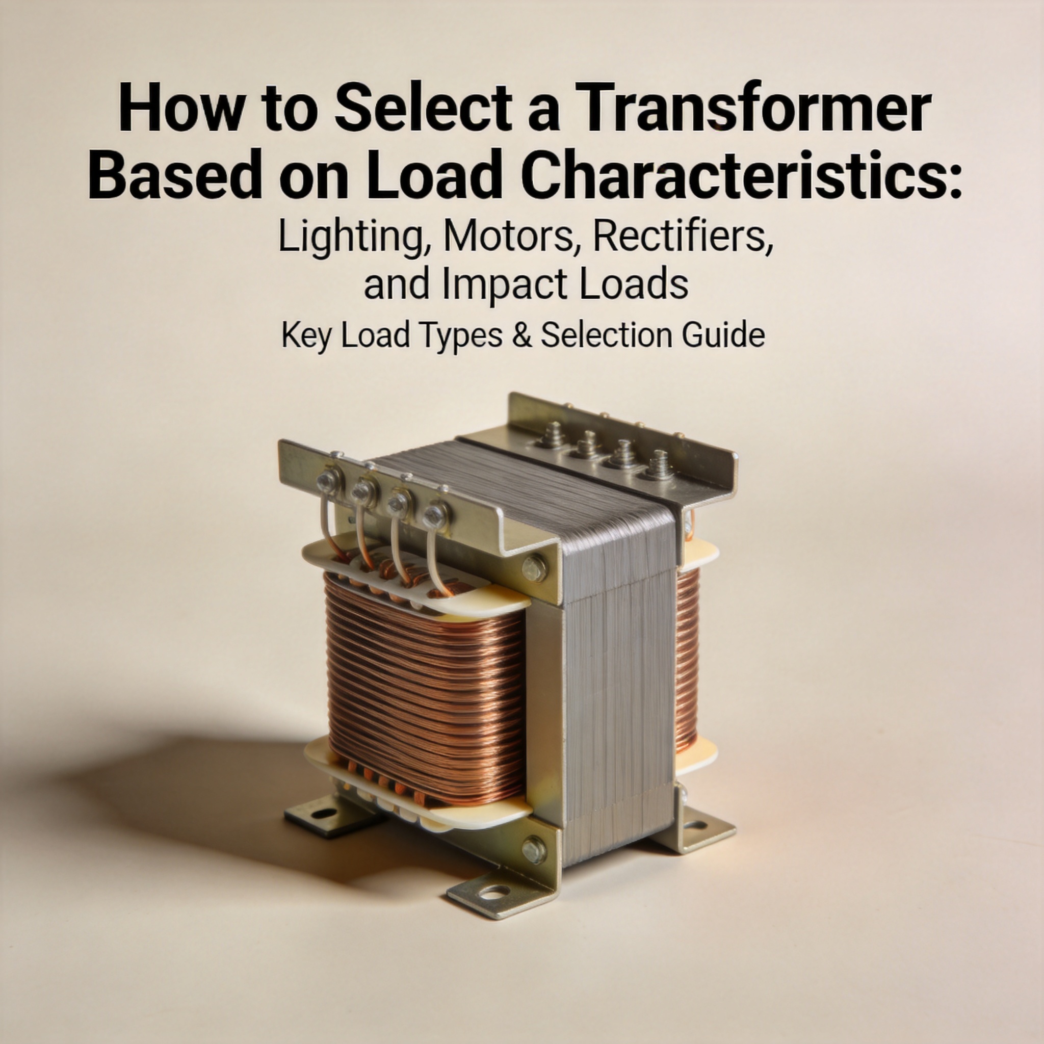
To select a transformer based on load characteristics, you do not size it from the total connected kW alone. You calculate the worst-case demand in kVA, then apply a load-specific factor: 1.25× for motors, 1.2–1.5× for rectifiers and VFDs, and 1.5–2.0× for impact loads. Lighting loads normally need no oversizing beyond standard code demand factors. The single most common failure is sizing on running current while ignoring inrush and harmonic heating.
By the end of this article you will be able to classify any load, calculate a required transformer kVA, apply the correct derating factor for each load type, and verify your result against inrush and harmonic limits.
Table of Contents
Why Load Type Changes Transformer Sizing
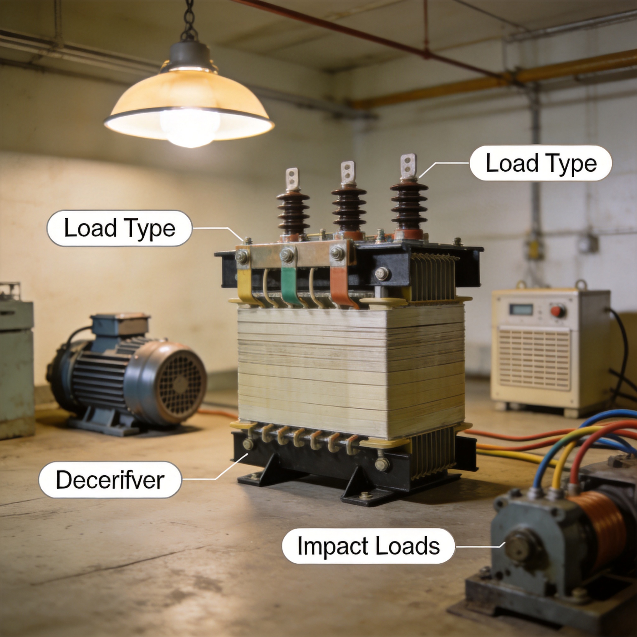
A transformer’s kVA rating is limited by winding temperature rise, not by instantaneous current. Two loads drawing the same 100 kW can heat the same transformer very differently because of power factor, harmonic content, and duration.
Four mechanisms drive the difference. First, power factor determines how many kVA you need for a given kW. Second, inrush current on motor starting can reach 6–8 times full-load amps for 0.1–10 seconds. Third, harmonic current from rectifiers and VFDs causes extra eddy-current and stray losses that standard 50/60 Hz ratings do not cover. Fourth, cyclic impact loads (presses, crushers, welding) produce repeated thermal cycling that accelerates insulation ageing.
IEEE C57.91 defines the thermal limits behind these effects and is the reference standard for transformer loading under non-sinusoidal and cyclic duty. IEC 60076-11 covers dry-type transformers with harmonic derating factors. Both are worth reading before you finalize a specification.
Load Classification Reference
| Load type | Typical PF | Inrush | Harmonic content | Sizing factor |
|---|---|---|---|---|
| Incandescent / resistive lighting | 1.00 | Low | Negligible | 1.0 |
| LED / electronic lighting | 0.90–0.95 | Moderate | High (3rd, 5th) | 1.1–1.25 |
| Induction motors | 0.80–0.90 | 6–8× FLA | Low | 1.25 + starting check |
| Rectifiers / VFDs / UPS | 0.85–0.95 | Moderate | Very high (5th, 7th, 11th) | 1.2–1.5 |
| Impact loads (presses, welders) | 0.60–0.80 | Very high | Moderate | 1.5–2.0 |
How to Select a Transformer: 7 Steps
Work through these steps in order. Each one produces a number you carry into the next.
- List every load with its nameplate data. Record kW or HP, voltage, power factor, efficiency, and duty cycle. For motors use the full-load amps (FLA) from the nameplate, not the running amps you measure on site.
- Convert each load to kVA. For single-phase: kVA = (V × A) / 1000. For three-phase: kVA = (√3 × V × A) / 1000. For motors given in HP: kW = HP × 0.746 / efficiency, then kVA = kW / PF.
- Apply the demand factor. Use NEC Article 220 or your local code. A typical industrial panel runs 0.7–0.9 demand factor; lighting in offices often 1.0.
- Apply the load-type sizing factor from the table above. This is the step most people skip.
- Check motor starting against transformer impedance. A rule of thumb: the largest motor’s locked-rotor kVA should not exceed the transformer’s kVA divided by its per-unit impedance, multiplied by the allowable voltage dip. For a 1000 kVA transformer at 5.75% impedance, short-circuit capacity is roughly 17,400 kVA. A 200 HP motor at 6× FLA draws about 900 kVA at start, giving roughly 5% voltage dip — usually acceptable.
- Check harmonic derating. Use the K-factor method (UL 1561) or the factor K from IEC 60076-11. If the calculated K-factor exceeds 4, specify a K-rated or oversized standard transformer.
- Round up to the next standard size and confirm the result against the actual load profile, not just the peak.
Worked Example: Mixed Industrial Panel
Assume a panel feeding 60 kW of LED lighting (PF 0.92), one 75 HP motor (efficiency 0.93, PF 0.86), and a 40 kW VFD-driven pump (PF 0.95, harmonic-rich).
- Lighting: 60 / 0.92 = 65.2 kVA × 1.15 (LED factor) = 75 kVA
- Motor: 75 × 0.746 / 0.93 = 60.2 kW; 60.2 / 0.86 = 70 kVA × 1.25 = 87.5 kVA
- VFD: 40 / 0.95 = 42.1 kVA × 1.35 = 56.8 kVA
- Total with 0.85 demand factor: (75 + 87.5 + 56.8) × 0.85 = 186 kVA
Round up to a 225 kVA standard transformer. Then verify motor starting: the 75 HP motor draws about 340 kVA locked-rotor. On a 225 kVA unit at 4% impedance, short-circuit capacity is 5,625 kVA, so voltage dip is roughly 6% — acceptable for most installations but worth confirming with the motor supplier.
Common Mistakes and Fixes
Mistake 1: Sizing on total connected kW
Symptom: The transformer runs above 80% load within weeks of commissioning and nuisance-trips on hot afternoons.
Fix: Always convert to kVA and apply demand plus load-type factors. A 500 kW connected load at PF 0.85 is already 588 kVA before any oversizing.
Mistake 2: Ignoring motor inrush
Symptom: Lights flicker every time a large motor starts, or the upstream breaker trips on start.
Fix: Calculate locked-rotor kVA and compare against transformer short-circuit capacity. If voltage dip exceeds 10% (or 15% for dedicated motor circuits), increase transformer size or add a soft starter.
Mistake 3: Using a standard transformer on a rectifier load
Symptom: Winding temperature runs 15–25 °C above design even at 70% nameplate load, and insulation fails early.
Fix: Calculate the K-factor. A typical six-pulse drive load gives K-factor 4–9. Either specify a K-rated transformer or oversize a standard unit by 1.3–1.5×.
Mistake 4: Treating impact loads as continuous
Symptom: Transformer passes thermal calculation but fails after 2–3 years on a press or welder circuit.
Fix: Impact loads cause cyclic thermal expansion. Apply the 1.5–2.0× factor and, where duty cycle is severe, use a transformer with lower temperature rise class (e.g., 80 K instead of 100 K).
Mistake 5: Forgetting future load growth
Symptom: You need a second transformer within 18 months.
Fix: Add 15–25% headroom at the design stage. The cost difference between one size and the next is usually far less than a second unit plus switchgear.
FAQ
What size transformer do I need for a 100 HP motor?
A 100 HP motor at 0.93 efficiency and 0.86 PF draws about 93 kVA running. Apply the 1.25 motor factor, giving roughly 117 kVA. Round up to a 150 kVA transformer, then verify starting: locked-rotor kVA is about 560 kVA, which on a 150 kVA / 4% unit produces a short-circuit capacity of 3,750 kVA and a voltage dip near 15%. If that is too high for your other loads, move to 225 kVA.
Can I use a standard transformer with VFDs?
Only if you verify the K-factor. Most six-pulse VFD loads produce K-factor 4–9. A standard transformer is rated K-1. Either specify a K-rated unit or oversize a standard transformer by the harmonic factor — typically 1.3–1.5×. Also confirm the transformer’s impedance is high enough to limit harmonic currents but low enough to avoid excessive voltage distortion.
What is the difference between K-factor and derating factor?
K-factor is a transformer rating (K-1, K-4, K-13, K-20) that describes its ability to handle harmonic heating without exceeding rated temperature rise. Derating factor is the multiplier you apply to a standard transformer’s nameplate kVA to find its usable capacity under harmonic load. They describe the same physics from opposite directions.
How do I handle a load that is both harmonic-rich and impact-type?
Apply both factors sequentially, not additively. First derate for harmonics (multiply by 1/0.7, i.e., 1.43×), then apply the impact factor (1.5–2.0×). The result is often 2.0–2.5× the running kVA. In these cases a K-rated transformer with a lower temperature rise class is usually more economical than a very large standard unit.
Does power factor correction reduce transformer size?
Yes, and it is often the cheapest option. Adding capacitors to bring PF from 0.80 to 0.95 reduces required kVA by about 16%. However, capacitors must not be applied on the load side of a VFD — they can resonate with the drive’s DC link. Install them on the line side or use a detuned filter.
What standard should I reference for sizing?
For thermal loading and cyclic duty, use IEEE C57.91. For dry-type transformers under harmonic load, use IEC 60076-11. For installation and demand factors in North America, use NFPA 70 (NEC) Article 220 and Article 450. These three documents cover the calculation, the derating, and the installation requirements respectively.
How much headroom should I add?
Add 15–25% above your calculated worst-case kVA. Less than 15% leaves no margin for ambient temperature above 30 °C or for load growth. More than 25% wastes capital and increases no-load losses, which you pay for continuously.



 English
 Français
 Español
 Deutsch