
Inhaltsübersicht
How the Thermostat and Fan Auto Start/Stop Logic Works
The controller reads three PT100 sensors, one per phase winding, plus optionally a fourth sensor for the core or ambient. Each sensor produces a resistance that the controller converts to a temperature. The controller then compares that temperature to four configurable thresholds: fan start, fan stop, high-temperature alarm, and over-temperature trip.
When the hottest winding reaches the fan start setpoint, the controller closes a relay that energizes the cooling fans. When the winding cools back down to the fan stop setpoint, the relay opens and the fans stop. This is a hysteresis loop, and the gap between start and stop prevents the fans from chattering on and off.
Typical factory defaults for an F or H class insulation system are shown below. Always verify against your transformer’s nameplate and the controller manual before changing anything.
| Function | Typical Setpoint | Relay Action |
|---|---|---|
| Fan start | 110 °C | Close fan relay |
| Fan stop | 90 °C | Open fan relay |
| High temp alarm | 130 °C | Close alarm contact |
| Over-temp trip | 150 °C | Open trip contact |
The hysteresis gap here is 20 °C. A gap below 10 °C causes short-cycling; a gap above 30 °C lets the winding run hotter than necessary between cycles. The trip relay typically wires into the breaker shunt-trip coil or a supervisory alarm input.
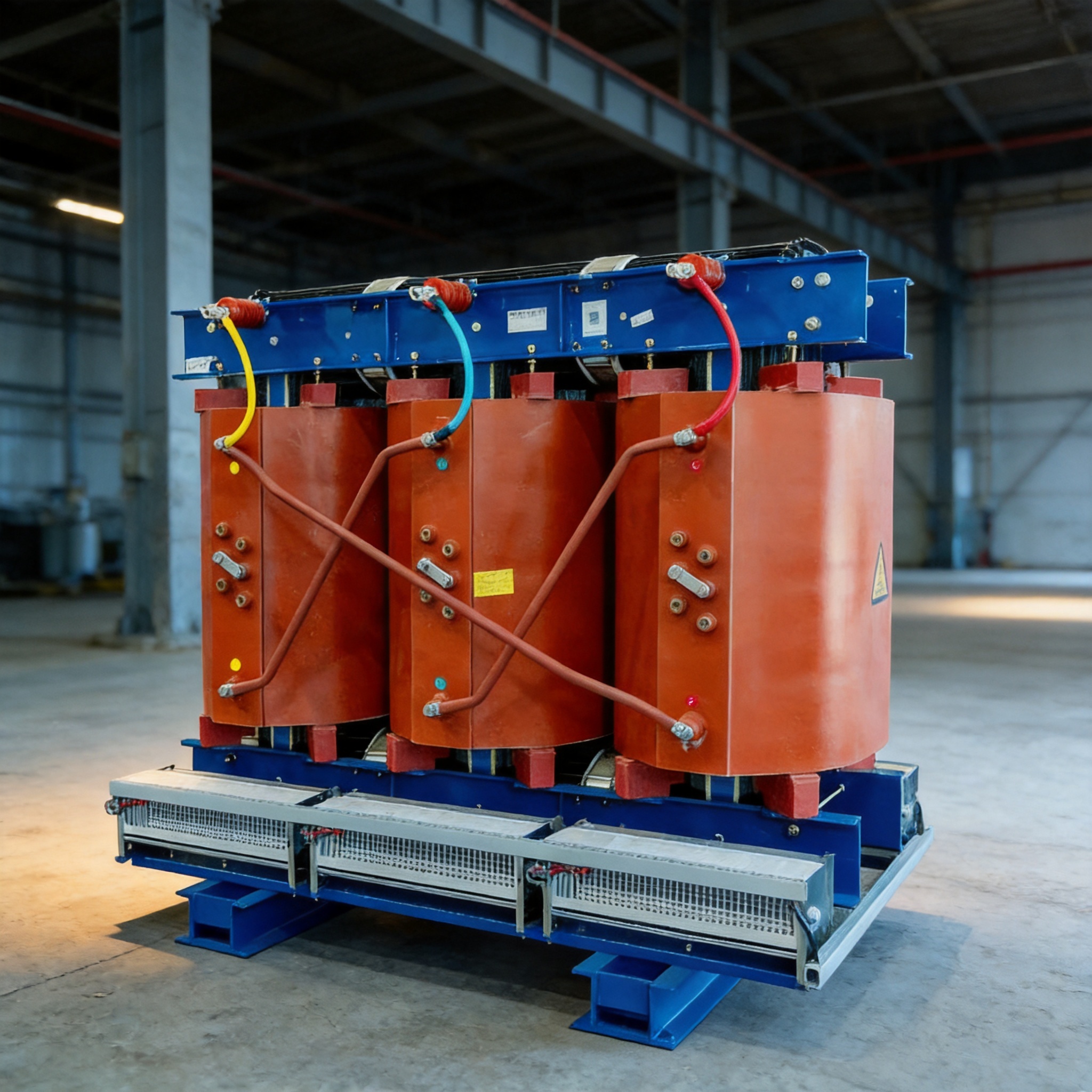
For a 30–5000 kVA SCB transformer with Class F or H insulation, these thresholds sit well below the insulation’s thermal limit, giving margin for overload conditions.
Step-by-Step: Configuring Auto Start/Stop Logic
Follow these steps in order. Each step assumes the transformer is de-energized and locked out unless stated otherwise.
- Isolate and lock out the transformer. Confirm zero voltage at the primary and secondary terminals with a rated meter before touching any wiring.
- Identify the PT100 sensor leads. On an SCB transformer these are typically three white or red twisted pairs emerging from the winding and routed to the controller’s sensor terminals. Label them Phase A, B, and C.
- Verify sensor resistance at ambient. A PT100 reads approximately 100 Ω at 0 °C and about 110 Ω at 25 °C. If a reading is open circuit or far off, the sensor or its lead is faulty.
- Connect sensors to the controller. Match Phase A, B, C to the corresponding terminals. Use shielded cable and ground the shield at the controller end only.
- Set the fan start setpoint. Enter the value from your nameplate or the table above (commonly 110 °C).
- Set the fan stop setpoint. Enter a value 15–25 °C below the start setpoint (commonly 90 °C).
- Set the alarm and trip setpoints. Enter the high-temp alarm (commonly 130 °C) and over-temp trip (commonly 150 °C) values.
- Wire the fan relay output. Connect the relay’s normally-open contact in series with the fan contactor coil and the control power supply. Confirm the contactor coil voltage matches the supply.
- Wire the alarm and trip contacts. Route the alarm contact to your supervisory system and the trip contact to the breaker shunt-trip or a lockout relay.
- Power the controller only (fans off). Confirm the display shows all three phase temperatures within a few degrees of each other and close to ambient.
- Test the fan relay manually. Use the controller’s manual output test to energize the fan relay. Confirm the fans start and the contactor holds.
- Simulate a temperature rise. If your controller supports simulation, drive the reading above the fan start setpoint and confirm the fans energize. Drive it below the stop setpoint and confirm they de-energize.
- Record the final setpoints on the commissioning sheet and photograph the controller display for the maintenance file.
After the transformer is re-energized, monitor the phase temperatures for the first few hours of load. A healthy SCB transformer under normal load typically stabilizes well below the fan start setpoint, so the fans should only cycle during peak load or high ambient conditions.
Häufige Fehler und wie man sie behebt
These are the failures seen most often during commissioning and maintenance. Each one lists the symptom first, then the fix.
- Fans short-cycle every few seconds. Symptom: the fan contactor chatters and the fans never reach steady speed. Cause: the fan start and stop setpoints are too close together, often within 5 °C. Fix: widen the gap to 15–25 °C. If the controller only allows a single setpoint, add an external hysteresis relay or replace the controller with one that supports separate start/stop values.
- Fans run continuously even when the transformer is cold. Symptom: fans stay on at ambient temperature. Cause: the fan relay output is wired to the normally-closed contact instead of normally-open, or the controller is in manual mode. Fix: move the wire to the normally-open terminal and confirm the controller is in auto mode.
- One phase reads much higher than the others. Symptom: Phase B shows 20 °C above A and C at no load. Cause: a loose or high-resistance sensor connection, or a sensor placed too close to a busbar joint. Fix: re-torque the sensor terminal, check lead resistance, and reposition the sensor if it is picking up radiated heat.
- Controller reads “open circuit” or a fixed high value. Symptom: display shows a fault code or a constant unrealistic temperature. Cause: broken PT100 lead or a sensor that has failed open. Fix: measure sensor resistance directly at the controller terminals. Replace the sensor if the reading is open.
- Trip contact never operates. Symptom: winding temperature exceeds the trip setpoint but the breaker does not open. Cause: the trip relay is wired to an alarm-only output, or the shunt-trip circuit is not powered. Fix: verify which relay is assigned to trip in the controller menu, then confirm control power is present at the shunt-trip coil.
One more issue worth checking: if the fans are wired to a single contactor but the controller has separate per-phase fan outputs, only one phase will control all fans. This is acceptable, but document it so the next technician does not assume independent control.
FAQ
What temperature should the fans start at on a dry-type transformer?
For Class F insulation, 110 °C is a common fan start point with a stop point around 90 °C. For Class H, some sites shift both values 10 °C higher. Always confirm against the transformer nameplate and the controller manual, because the correct value depends on the insulation class and the specific design.
Can I set the fan start and stop temperatures to the same value?
No. If start and stop are equal, the fans will cycle on and off rapidly around that temperature, wearing out the contactor and motor. Keep at least a 15 °C gap.
Why do my fans run even when the transformer is lightly loaded?
Either the setpoints are too low, the fan relay is on the wrong contact, or the controller is in manual override. Check the display for a manual indicator first, then verify the relay wiring.
What is the difference between the alarm and trip setpoints?
The alarm setpoint closes a contact that signals a supervisory system or annunciator, warning you that the winding is running hot. The trip setpoint opens or closes a contact that de-energizes the transformer through the breaker, protecting the insulation from damage. The trip point is always higher than the alarm point.
How often should I test the auto start/stop logic?
Test the fan relay and sensor readings at every scheduled maintenance interval, and always after any controller replacement or setpoint change. A simple manual relay test plus a sensor resistance check takes about ten minutes and catches most failures before they cause a trip.
For additional guidance on dry-type transformer testing and temperature limits, refer to IEEE standards and the applicable IEC 60076 series documents.

 English
 Français
 Español
 Deutsch