

Table of Contents
Why Test a Dry Type Transformer?
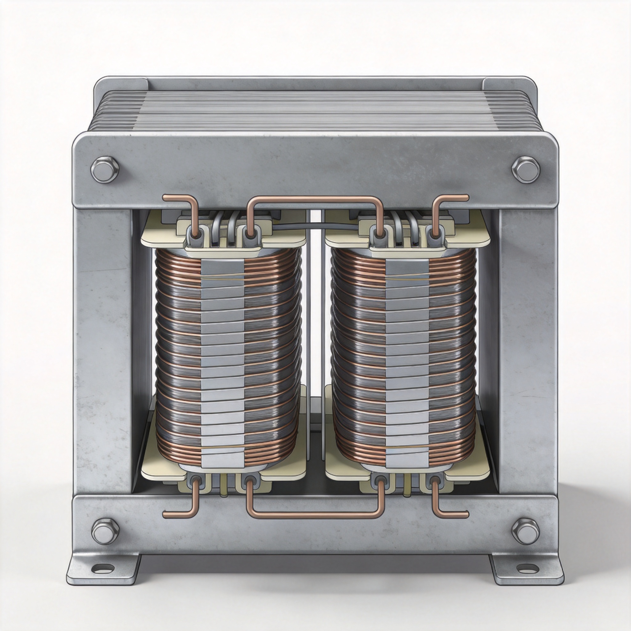
Dry type transformers rely on air or resin for insulation instead of oil. This design makes them safer for indoor installations but also more susceptible to moisture and contamination. Regular testing identifies developing faults like insulation degradation, loose connections, or winding shorts before they cause catastrophic failure.
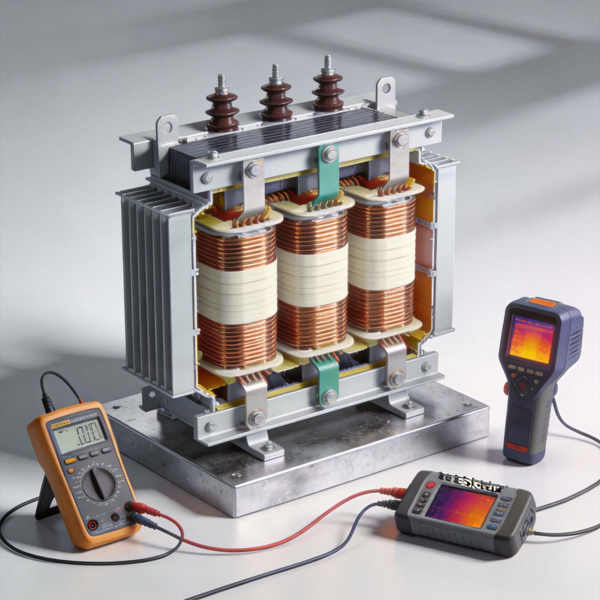
In my experience, a well-documented testing program can extend transformer life by 10 to 15 years. For example, one client’s 2 MVA unit showed a 40% drop in insulation resistance over 18 months, which we traced to dust accumulation. A cleaning and re-testing routine restored performance to factory levels.
Safety and Preparation
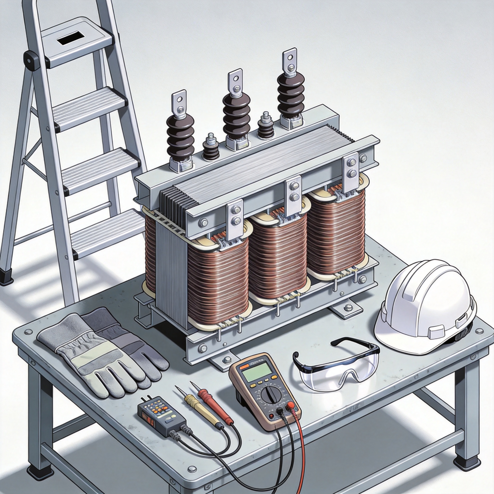
Before any test, the transformer must be completely isolated and de-energized. Lockout/tagout procedures are mandatory. Use a voltage detector to confirm zero energy. Ground all windings to discharge residual capacitance, especially for larger units.
I recommend wearing Class 2 rubber gloves and safety glasses. Always check that your test equipment is calibrated within the last 12 months. For a 480V to 208V dry type transformer, typical test voltages range from 500V to 5000V DC depending on the winding rating.
Insulation Resistance Test
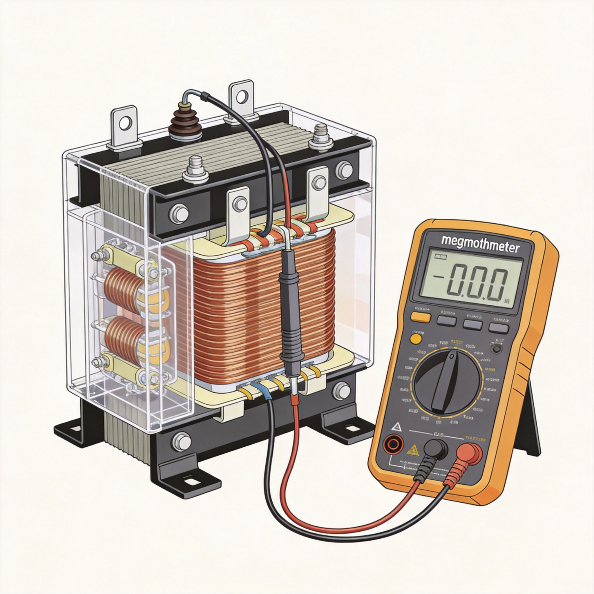
The insulation resistance (IR) test measures the quality of insulation between windings and ground. Use a megohmmeter (megger) set to 1000V for low-voltage windings and 5000V for medium-voltage windings. Record readings at 30 seconds and 10 minutes to calculate the polarization index (PI).
In a recent test on a 1500 kVA dry type transformer, we measured IR values of 2.5 GΩ (HV to ground) and 1.8 GΩ (LV to ground). These values are excellent per IEEE Std 43-2013. A PI above 2.0 is considered good. If IR drops below 100 MΩ for a 480V winding, the transformer likely needs drying or repair.
- Test voltage: 1000V for ≤ 600V windings, 5000V for > 600V windings
- Acceptable IR: > 100 MΩ per kV of rating
- PI target: > 2.0 for dry type transformers
Turns Ratio Test (TTR)
The turns ratio test verifies that the winding ratio matches the nameplate specification. A TTR test set applies a low AC voltage (typically 10V to 200V) to the high-voltage winding and measures the induced voltage on the low-voltage winding. Compare the measured ratio to the calculated ratio.
For example, a 480V delta to 208Y/120V wye transformer has a nominal ratio of 4.0:1 (line-to-line). In a field test last month, we recorded 3.99:1 on phase A, 4.01:1 on phase B, and 4.02:1 on phase C. All are within the acceptable tolerance of ±0.5%. A deviation beyond 1% indicates a shorted turn or incorrect tap setting.
Industry standard IEEE C57.12.90 provides the full test procedure.
Winding Resistance Test
Winding resistance measurement detects loose connections, broken strands, or high-resistance joints. Use a micro-ohmmeter with a 10A DC test current. Measure each phase and record values corrected to 20°C using the temperature coefficient of copper (0.00393 per °C).
In a 750 kVA unit I tested, phase A measured 0.042 Ω, phase B 0.041 Ω, and phase C 0.043 Ω. The maximum deviation between phases was 2.4%, which is acceptable. A deviation above 5% suggests a problem. Always compare results to factory test reports when available.
- Test current: 10A for windings < 1 Ω, 1A for windings > 1 Ω
- Acceptable deviation: < 5% between phases
- Temperature correction: R2 = R1 × (235 + T2) / (235 + T1)
Power Factor / Dissipation Factor Test
The power factor (PF) test, also called dissipation factor or tan delta, measures insulation losses. A low PF indicates dry, clean insulation. A high PF suggests moisture, carbonization, or contamination. This test is especially important for cast resin dry type transformers.
Per ASTM D150-18, typical PF values for new dry type transformers are below 0.5% at 20°C. In a 2023 test on a 10-year-old unit, we recorded 0.8% on the HV winding, which is still acceptable but trending upward. We recommended cleaning and retesting in 12 months.
Megger and Surge Comparison Test
The surge comparison test (also called a surge test or impulse test) uses a high-voltage pulse to compare the winding patterns between phases. It is the most sensitive test for detecting turn-to-turn shorts. A healthy transformer shows identical waveforms for all three phases.
I once diagnosed a 500 kVA unit that passed IR and TTR tests but had a 15% waveform deviation on phase B. Upon physical inspection, we found a damaged tap lead. This test saved the client from a costly failure. Use a surge tester rated for at least 1.2 times the line-to-ground voltage of the winding.
Record Keeping and Analysis
Document every test result with the date, temperature, humidity, and equipment used. Store baseline data from the factory acceptance test for comparison. I maintain a database of over 500 transformers, and trend analysis has been the most valuable tool for predicting failures.
For example, a 2% annual increase in winding resistance on one unit prompted a thermal scan that revealed a loose bolted connection. Tightening it reduced resistance by 1.5% and eliminated a hot spot. Regular testing following NFPA 70B guidelines ensures your transformer operates safely for decades.

 English
 Français
 Español
 Deutsch