
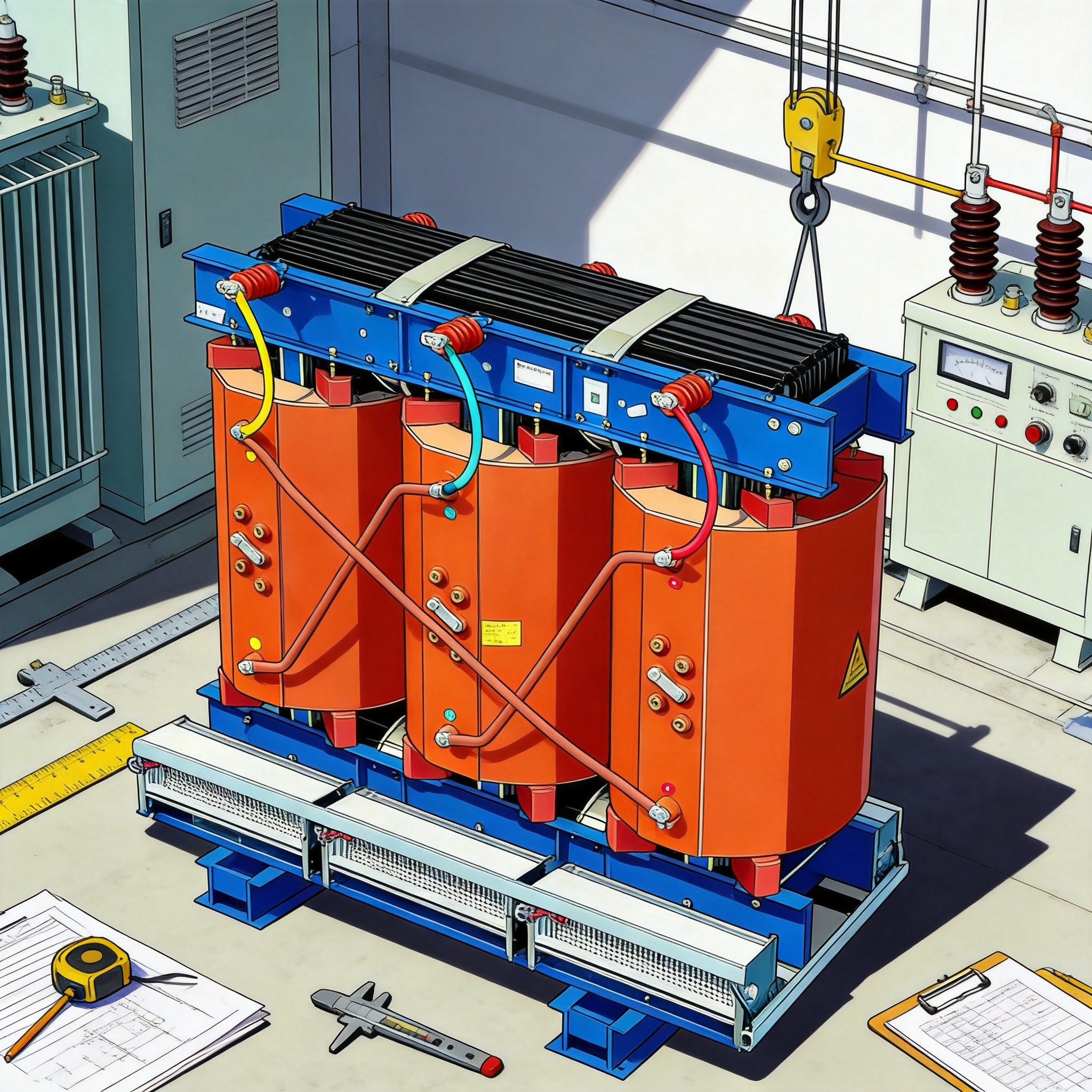
Operating efficiency of a dry-type transformer is the ratio of output power to input power at a given load, and you calculate it by adding two loss components — no-load loss (P0) and load loss (Pk) — to the output. No-load loss stays constant whenever the transformer is energized; load loss changes with the square of the load current. Once you have both figures from the nameplate or a test report, efficiency at any load point takes one formula and about two minutes of arithmetic.
After reading this guide, you will be able to read P0 and Pk from a nameplate, compute efficiency at 25%, 50%, 75%, and 100% load, find the load at which efficiency peaks, and check your result against the loss data that SCB-series dry-type transformers are required to publish.
Table of Contents
How No-Load and Load Losses Work
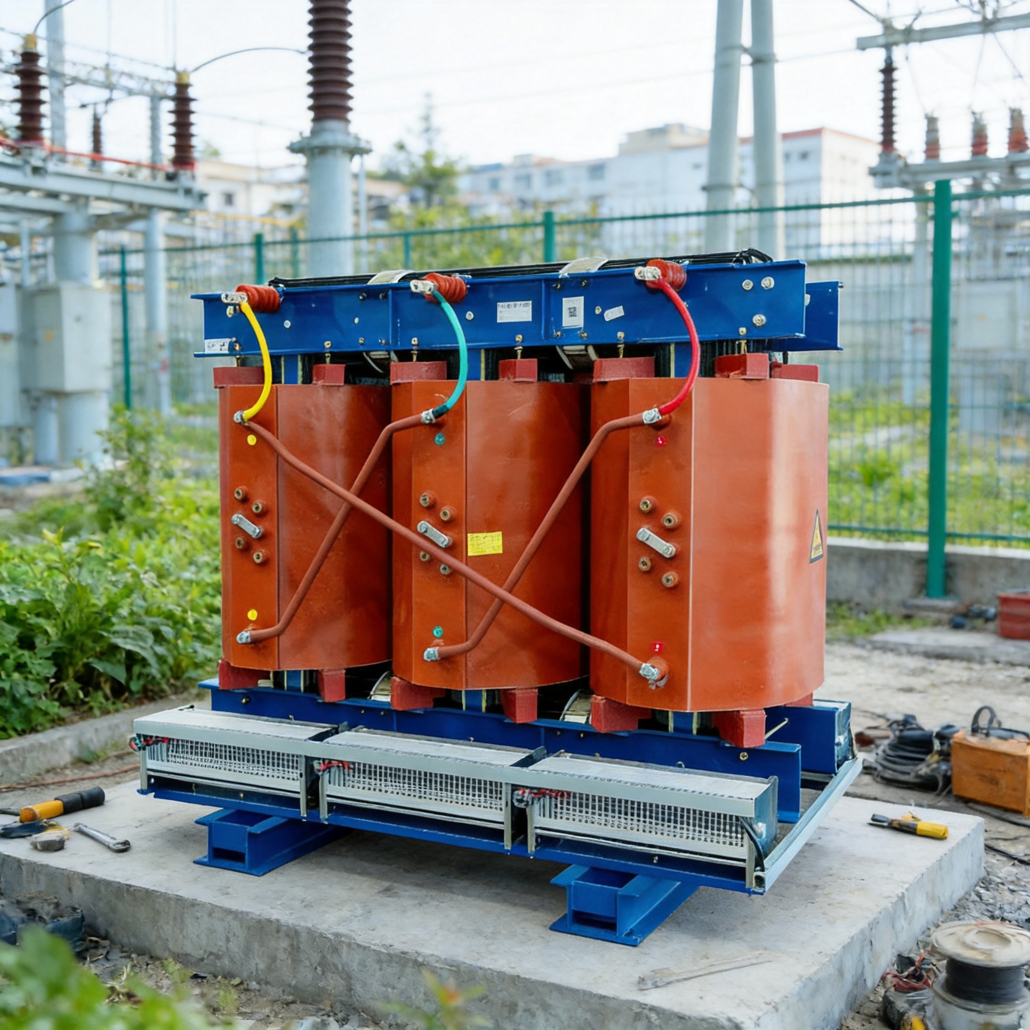
No-load loss, written P0 and measured in watts or kilowatts, is the power the transformer consumes when the secondary is open-circuited and rated voltage is applied to the primary. It comes almost entirely from hysteresis and eddy currents in the magnetic core, which is why it is also called core loss or iron loss. Because the core flux is set by the applied voltage, P0 is essentially constant from no load to full load — it does not disappear when the load is zero.
Load loss, written Pk, is the power dissipated when rated current flows through the windings, and it is dominated by I²R heating in the copper or aluminum conductors. It is measured by short-circuiting the secondary and raising the primary voltage until rated current circulates. Because the heating scales with the square of current, load loss at any fraction x of rated load equals Pk × x². At half load, load loss is only 25% of the nameplate Pk value.
This split matters because the two losses behave in opposite ways as load rises. P0 is a fixed tax you pay the moment the transformer is energized; Pk grows quadratically and eventually dominates. Peak efficiency occurs at the load where P0 equals x²Pk, which works out to x = √(P0/Pk). For a typical distribution dry-type transformer, that point usually falls between 40% and 60% of rated load, which is exactly where many real installations operate.
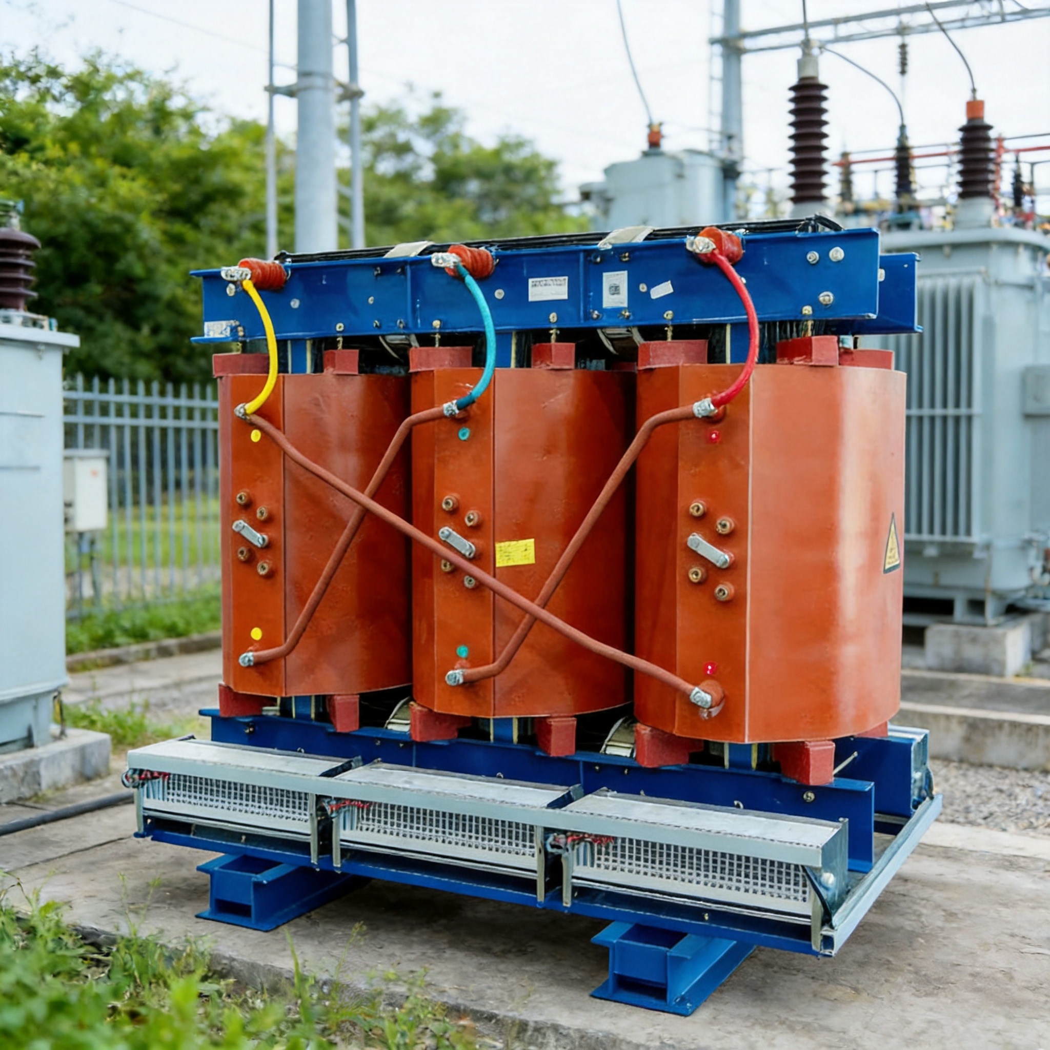
Dry-type transformers in the SCB family are rated from 30 kVA to 5000 kVA with high-voltage windings from 6 kV through 35 kV and low-voltage windings from 0.38 kV through 0.72 kV, per the reference specification. Insulation classes F and H are available, and impedance ranges from 4% to 10%. Units are built to EN 50588, IEC 60079, UL, and CE, all of which require declared loss values, so the numbers you need should always be on the nameplate or in the type test report.
How to Calculate Operating Efficiency: 6 Steps
Work through the steps in order. Each step produces one number you carry into the next, so you can stop at any point and still have a usable result.
- Record the transformer rating and loss values. From the nameplate or test report, write down rated capacity S (kVA), no-load loss P0 (W or kW), and load loss Pk (W or kW). For example: S = 1000 kVA, P0 = 1700 W, Pk = 10500 W. Confirm both losses are in the same unit before continuing.
- Choose the load fraction x you want to evaluate. Use a decimal: 0.25 for 25% load, 0.5 for 50%, 0.75 for 75%, 1.0 for full load. If you want the peak-efficiency point instead, skip to step 6.
- Compute the output power at that load. Output in watts = S × 1000 × x × power factor. Use the actual power factor of your load; if unknown, use 0.8 as a documented assumption and state it in your result. At 1000 kVA, 50% load, and 0.8 PF: 1000 × 1000 × 0.5 × 0.8 = 400,000 W.
- Compute the load loss at that load. Pk(x) = Pk × x². At 50% load: 10,500 × 0.25 = 2,625 W. This is the single most common place beginners go wrong — the loss does not scale linearly.
- Compute efficiency. Efficiency η = output ÷ (output + P0 + Pk(x)). Using the numbers above: 400,000 ÷ (400,000 + 1,700 + 2,625) = 400,000 ÷ 404,325 = 0.9893, or 98.93%.
- Find the peak-efficiency load. Solve x = √(P0 ÷ Pk). With P0 = 1700 W and Pk = 10500 W: x = √0.1619 = 0.402, so peak efficiency occurs at about 40% load. Efficiency falls off slowly on either side of this point, so a transformer sized for 50–60% average loading will run near its best efficiency most of the time.
The table below applies the same method across four load points for the 1000 kVA example, assuming a 0.8 power factor. Every figure is reproducible from steps 1–5.
| Load | Output (W) | Load loss Pk×x² (W) | Total losses (W) | Efficiency |
|---|---|---|---|---|
| 25% | 200,000 | 656 | 2,356 | 98.84% |
| 50% | 400,000 | 2,625 | 4,325 | 98.93% |
| 75% | 600,000 | 5,906 | 7,606 | 98.75% |
| 100% | 800,000 | 10,500 | 12,200 | 98.50% |
Notice that efficiency is worst at full load in this example, not at part load, because the quadratic load loss finally outpaces the fixed core loss. If you repeat the calculation with P0 = 3000 W and Pk = 8000 W, peak efficiency shifts to x = √0.375 = 0.61, or 61% load. That is the whole decision rule: a transformer with high core loss relative to copper loss peaks at a higher load fraction.
For annual energy cost, multiply each loss by the hours it applies. A transformer energized 8,760 hours per year at a constant 50% load loses (1700 + 2625) × 8760 = 37.9 MWh per year. At 100% load for the same period the figure is (1700 + 10500) × 8760 = 106.9 MWh. This is why part-load operation, not nameplate efficiency alone, drives real operating cost.
Common Mistakes and How to Fix Them
Mistake 1: Scaling load loss linearly with load. Symptom: your calculated losses at 50% load are half of nameplate Pk, and efficiency looks better than the data sheet suggests. Fix: always square the load fraction. At 50% load, Pk is 25% of rated, not 50%. Recompute with Pk × x² and the numbers will match the test report.
Mistake 2: Mixing watts and kilowatts. Symptom: efficiency comes out at 99.99% or 89%, both implausible for a distribution transformer. Fix: convert everything to watts before dividing. A nameplate reading “P0 = 1.7 kW, Pk = 10.5 kW” becomes 1700 W and 10500 W. Keep output in watts as well.
Mistake 3: Using rated power factor instead of actual power factor. Symptom: calculated efficiency is consistently higher than measured in the field. Fix: output power depends on the real power factor of the connected load. If you do not know it, measure it or use a stated assumption such as 0.8 and label the result accordingly. Never silently use 1.0.
Mistake 4: Ignoring the harmonic content of the load. Symptom: measured load loss exceeds the nameplate Pk even at rated fundamental current. Fix: harmonic currents raise the effective RMS current and add stray and eddy losses in the windings. If your load is non-linear, treat the calculated efficiency as an upper bound and consult a qualified professional for a harmonic-loss assessment.
Mistake 5: Reading loss data from a different rating or temperature. Symptom: your result disagrees with the manufacturer’s published efficiency curve. Fix: load loss is normally corrected to a reference temperature (often 75°C or 120°C depending on the standard). Use the loss values at the same reference temperature as the efficiency figure you are comparing against, and note the reference temperature in your calculation.
FAQ
Do I need a lab test to get P0 and Pk?
No. For any transformer built to EN 50588, IEC 60079, UL, or CE, the declared no-load and load losses appear on the nameplate or in the routine test report supplied with the unit. If the nameplate only gives efficiency, ask the supplier for the loss values in watts; you cannot back-calculate both losses from a single efficiency number.
Why is my transformer most efficient at part load instead of full load?
Because core loss is fixed while copper loss grows with the square of load. Below the crossover point, adding load recovers more output per watt of total loss; above it, the quadratic copper loss takes over. The crossover is x = √(P0/Pk), typically 40–60% for SCB-type distribution transformers.
Does a higher insulation class change the losses?
Class F and Class H insulation primarily affect the permissible temperature rise and the maximum ambient the unit can tolerate. They do not by themselves set P0 or Pk. However, a design that uses more conductor material to stay within a hotter insulation class will usually show lower load loss, so always compare the actual declared values rather than the insulation class alone.
How does impedance affect the calculation?
Impedance, which for SCB units ranges from 4% to 10%, sets the short-circuit current and voltage regulation, not the efficiency formula. It matters indirectly: a higher-impedance design often has higher load loss for the same rating. Use the declared Pk value rather than trying to derive it from impedance.
What load should I size a transformer for to maximize efficiency?
Size so that your expected average load sits near x = √(P0/Pk). For a unit with P0 = 1700 W and Pk = 10500 W, that is roughly 40% of nameplate. In practice, sizing for 50–70% average loading keeps you close to peak efficiency while leaving headroom for load growth and motor starting.
You can verify any of these calculations against the loss data published for your specific unit and, where harmonic or high-altitude conditions apply, against the applicable standard — EN 50588, IEC 60079, UL, or CE — or with a qualified professional.






 English
 Français
 Español
 Deutsch